...making Linux just a little more fun!
By Cherry George Mathew
|
...making Linux just a little more fun! |
By Cherry George Mathew |
It's hectic at work today. You have a hundred emails to reply to. There's that quality analysis report to submit this afternoon, a business presentation to prepare for the PR team, and a whole bunch of code to sift through for formatting errors. And then there's that favourite TV program that you can't miss out on by any chance. What do you do ? Switch on that TV tuner card of course. And watch the TV program in a window all by itself at the top right corner of your computer screen. All work and no play indeed! Now you can minimize the video window out of sight whenever the boss decides to take a peek over your shoulder. Or you could have it running full screen and beckon at him to come over and have a look if he's a fan too. ;-) Ah! The vagaries of technology!
The Linux platform supports a good number of tuner cards, as well as web cameras and an assortment of such multimedia devices. And as in every other operating system, the tasks of application programs and the kernel proper, are well demarcated and cut out distinctly. Video4Linux (or V4L), as the technology is called, is still evolving from a draft version 1, to a more robust version 2. On the way, lots of device drivers have been developed, primarily around the brooktree chip-set, but now increasingly around other models as well. Application programmers focus on preparing easy GUI based interfaces for the user, either for watching TV, or recording to disk or decoding and reading teletext and so on and so forth. For TV viewing, tasks such as preparing a window of just the right size on screen, requesting the relevant device driver to fill it in with live video (overlay), resizing the viewing area and asking the device driver to adjust the overlay size accordingly, passing on user requests to tune into a specific channel or to change the input from tuner to AV mode, or simply mute sound - these are responsibilities of the application programmer. The application therefore sits as a front end to the tuner driver, and passes on requests from the user to the driver in a previously agreed upon manner, called an Application Programmers Interface (API).
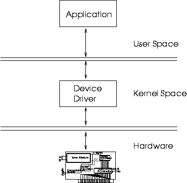
This is explained in detail later.Device Driver programmers, on the other hand, concentrate on translating user requests as mentioned above, into hardware instructions to the specific tuner card. They also make sure that they communicate with applications using the V4L API. Device drivers therefore, sit in between the hardware and the application, taking commands from them, translating them, and passing them on to the underlying hardware, in machine specific jargon.
Over the next couple of pages, you and I are going to try each others'
patience . We're going to show each other, among other things, how
TV tuner cards work, what they're made of, what types there are, how
to make them work in Linux etc etc etc. I say "show each"
other, because in attempting to put this article together, I've had
to do a bit of research myself, and that's because of you, dear Reader!
This is mutual then; so grab a piece of paper and a pen, sit back,
and read on.
Warning: Do not nod off. You're going to have a test afterward.
Keywords: PCI bus, I2C bus, IF (Intermediate Frequency), Video Processor,
Frame Buffer, DMA, IRQ.
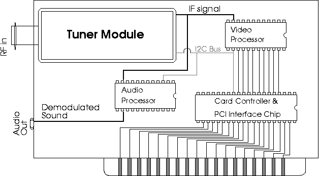
Alright, lets find out what a TV tuner card looks like. Typically, you'd spy at least three functional chips on board.
The tuner "chip", is actually a whole board with all the Radio Frequency Components mounted on it, and nicely wrapped up in silver foil, I mean, protective shielding. Take a look at the diagram. Tuner modules come in distinctive packaging, which often look very much like each other. Your antenna cable goes right into the socket at one end of the tuner module. The job of the tuner module, is to do all the Radio Frequency mixing magic, which tunes into a specific TV programme. Whatever frequency the TV programme be on, it is converted into a pre-determined intermediate frequency (IF). This "pre-determined" frequency is actually a real mess, because of historic (political ?) reasons. Each TV system (eg: PAL, SECAM, NTSC, etc.) has a unique IF. Whatever the IF is, the tuner takes care of one, and only one job - it takes in all the zillions of possible frequencies of radio waves in the universe, and at your command, filters out just the right TV programme for you. In the ''I2C section" 5, we'll find out how you "command" the tuner module to tune into your favourite Sports Channel.
The IF which comes from the tuner module, needs to be decoded, and transformed into a viewable format. This is the job of the Video Processor. Viewable Formats, again, due to historic reasons, come in various shapes and sizes. You've got the plain old bitmap format, palletized and planarized (uh, whatever does that mean ?) VGA format, RGB (for Red Green Blue) format, YUV Format (and its subtle variants) and of course, various proprietary formats. If you're keen at reading between the lines, you might have guessed that the "transformation" mentioned above, includes demodulation and Analog to Digital Conversion - which is the whole point of the TV tuner card anyway. When you watch TV on your Computer Screen, what you're actually looking at is Digitized Video Data from the Video Processor being displayed by your VGA adapter. Right, lets break that up into two steps:
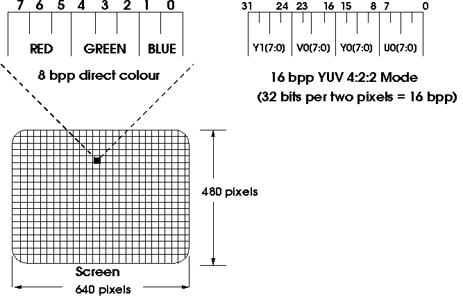
Any data within the frame buffer, is immediately reflected on the screen. This is the job of the VGA controller. If you want to display something on the screen, all you need to do is to dump some data into the frame buffer. Voila! You can immediately see it on screen. On most platforms, this will involve just a plain memory to memory copy, because the frame buffer is mapped into the physical memory address space, just like any other RAM. However on a system which implements some sort of memory protection, applications may not be allowed direct access to system RAM. In Linux, this is controlled by means of the mmap() system call in conjunction with the /dev/ram device node or the frame buffer device driver. Check the manual page of mmap() for details. Of course, for this to work sensibly, the VGA controller has to agree with you about what you wanted to display, and what you wrote into the frame buffer, and where. This is done by "setting the VGA mode". By setting the VGA "mode", the meaning of every bit of data in the frame ram, is now known to the VGA controller. For example, if the VGA mode is set to "640x480" at 8 bpp. The VGA controller knows two things about the display:
Picture then, the typical tuner card in question. It has been instructed to tune into a particular channel, capture the video data from it pixel by pixel into some digital format (eg: 8 bpp or YUV), and to dump it into RAM. This procedure is called "video capture". Here are a few possibilities of video capture:
Tuner Cards typically handle sound in two different ways. The first method uses the audio processor to demodulate sound from the IF (IF contains both audio and video information). The audio signal thus obtained is routed to an external audio jack, from where one would need to re-route it to the line input of a separate sound card by means of a suitable external cable. If you're not wealthy enough to own a sound card, the line input of your hi-fi set will do :-).
The second approach is for the audio processor to demodulate sound from the IF, convert it into Digital Samples, and use techniques such as DMA (DMA is explained in the section on "PCI buses") to move these Samples to the sound card via the internal system bus (eg: The PCI bus), and from there, to use the sound card to reconvert the digital samples back to the audio signal. This method is more complicated, but more flexible, as the TV sound levels are controllable on the tuner card itself. The first method can avail of that luxury only by talking to the sound driver of the separate sound card. Either way, let's sum up our requirements, and what is required of us as competent device driver writers for tuner cards.
Alan Cox has written an excellent article on the Video For Linux API for capture cards in Linux. It comes with the kernel documentation (Documentation/DocBook/videobook.tmpl)2 and covers many issues connected with the Video4Linux API. What it does not cover are details of the tuner capture process. Although attempting to cover details about all varieties of TV capture devices in a single article is impossible, a good share of the tuner cards (I cannot vouch for web cameras, etc, which plug into the USB port) available may be expected to conform to what is presented here.
linux/videodev.h3 is the authoritative reference for the V4L API. We will therefore avoid a detailed description of the V4L API here. Any conceptual details about it may be made out from the document by Alan Cox mentioned above. Moreover the V4L API is an evolving standard. What holds good today, may not be applicable tommorow.
First, lets take a look at the mechanism involved in communication between application and device driver. If you already know about character devices, this is a repetition, and you may safely skip this topic.
In every Unix system, the /dev subdirectory holds special files called device nodes. Each device node is associated with a specific device number registered in the kernel. In Linux, the video4linux driver is registered as device number 81. By convention, the name of the node associated with this device number is /dev/video0. See (Documentation/devices.txt) for details about numbering device nodes. The node /dev/video0, if nonexistent, may be created with the mknod command from the root shell as shown below:
#include <stdio.h>
#include <stdlib.h>
#include <sys/types.h>
#include <sys/stat.h>
#include <fcntl.h>
main(){
char *buffer;
/* Lets allocate as big a buffer as we can. */
buffer = malloc(65535);
/* Open the device node for reading */
if((fd = open("/dev/video0", O_RDONLY))<0)
fprintf(stderr, "Sorry, error opening device /dev/video0\n");
exit(-1);
}
/* Read until program is killed or device runs out of Data (unlikely). */
while( read(fd, buffer, 65535)) write(0, buffer, 65535);
free(buffer);
}
Want to switch on the video display ? Do a
ioctl(fd, VIDIOCSAUDIO, &v);
int video_exclusive_release(struct inode *inode, struct file *file);
int video_usercopy(struct inode *inode, struct file *file, unsigned int cmd, unsigned long arg, int (*func)(struct inode *inode, struct file *file, unsigned int cmd, void *arg));
What we can do, then, is to focus our energies on writing code to program the tuner hardware to do various things like start capture, switch on sound, copy video data back and forth, etc. Most V4L ioctls boil down to tackling these problems anyway. Finally, when everything is ready, we could go about bridging the latest greatest V4L API with our underlying code. This is standard engineering practice.
--------------- Snippet -------------------
Brigadier to Engineer: "Lieutenant, I want that bridge up and ready by nightfall. "
Engineer: "Uh, that's impossible sir. We need to take measurements on the ground and order the parts from supplies before we can even think of starting to build. That'll take at least a couple of weeks Sir!."
Brigadier: "So there are no struts or screws, no angle bars or I joints, absolutely nothing with you to start work immediately ????
Engineer: "Uh, no sir, I never thought we'd need spare parts at such short notice...."
Sound of Gunshot.
End of Take 1.
--------------- End of Snippet ----------------Let's begin building the parts.
One part of the driver is concerned with acquisition of video data, ensuring that the tuner module is properly tuned in, that the video processor is decoding the correct standard (eg: PAL, NTSC etc.), that picture properties such as brightness, hue, saturation and others supported by the video processor hardware is adjusted, properly fine tuned or set to default values. Sound Acquisition can also be the responsibility of this part of the driver. These are described in detail in the section on I2C.
The other part of the driver is concerned with making sure that the acquired data is displayed properly on the screen. This part of the driver has to ensure that if video is viewed in a window, overlapping issues with windows of other applications are handled correctly. Details of parameters which get affected when the video window is resized or dragged to another location, such as pitch of the video window, number of lines acquired, number of pixels acquired etc are the responsibility of this section of the driver. Lets take a look at the window overlap problem, in more detail. In a windowing environment such as Xwindows, video overlay needs to be implemented in a window. The overlap problem begins the moment a corner of another application window overlaps a part of the video window.
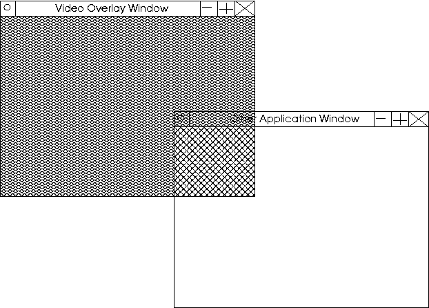
There are two options here:
What we can do then, is to begin writing routines which do little
things like setting the chroma key, setting the size of the video
window, positioning the window properly, etc. The best way to learn
such things is by example. We'll base our study on a few code snippets
from my unofficial and partly working driver for the Pixelview Combo
TV plus. This is a simple card, as simple as tuner cards can get to
be. The Tuner Module, video processor and VGA controller, all sit
on the same card. This card is plugged into the PCI slot, and doubles
both as a tuner card, and as a VGA display card.
Card Description:
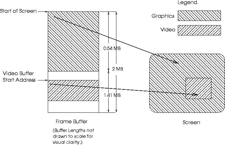
The video buffer may be located anywhere within the frame buffer,
but typically, it is located at the end of the frame buffer. This
keeps captured video data samples from overwriting graphics samples
that were already present in the frame buffer and vice-versa.
Let us illustrate with an example:
| Frame buffer size | = | 2MB |
| Display mode | = | 640x480 @ 16bpp. |
| Total memory required for VGA display | = | 640 x 480 x 2 bytes |
| = | 614400 bytes | |
| = | 0.59 MB |
| Unused Memory at the end of the Frame buffer | = | 2MB - 0.59MB |
| = | 1.41 MB |
The hardware window interprets and displays data within its jurisdiction, entirely differently from what the VGA mode dictates. The size and location of this video window, can be changed by programming relevant VGA registers. The GD-5446 has three sets of registers namely: control registers , graphics registers, and sequence registers . Each of these VGA registers is accessed by multiple reads and writes to hardware ports, and are hence encapsulated in specialized functions. I've named them gd_read_cr(), gd_write_cr() and so on. This improves readability of the code, and reduces the chances of error. Here are a few routines from my driver. I've stripped them down for brevity:
#define GD_SR_OFFSET 0x3c4
#define GD_GR_OFFSET 0x3ce
#define GD_CR_OFFSET 0x3d4
/* Adapter - Low level functions */
unsigned value;
io_writeb(reg, gd_io_base + GD_CR_OFFSET);
value = io_readb(gd_io_base + GD_CR_OFFSET + 1);
return value;
}
Here are a few higher level functions
void gd_enable_window();
static void gd_set_window(,,,);
void gd_set_pitch(
{
CR3C = gd_read_cr(card_p, 0x3c);
CR3D = gd_read_cr(card_p, 0x3d);
/* CR3C[5] = offset[11], CR3D = offset[10:3]*/
gd_bit_copy(&CR3C, 5, &offset, 11, 11);
gd_bit_copy(&CR3D, 0, &offset, 3, 10);
gd_write_cr(card_p, CR3C, 0x3c);
gd_write_cr(card_p, CR3D, 0x3d);
gd_write_cr() is used to write a value into a specified VGA register. Please ignore the variable card_p for the moment. It is a structure where global state information about the driver is stored. card_p is use by gd_write_cr for book keeping purposes only. gd_write_cr(card_p, CR3C, 0x3c) will write the contents of the variable CR3C into the control register 0x3c. (don't be fooled by the name CR3C, its as much a variable as 'unsigned long foo' is.)
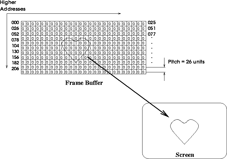
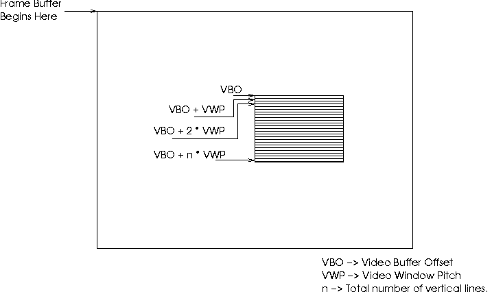
In the general case of a tuner card, where the VGA controller does not provide a separate hardware video window, the video processor will have to dump frames right into the middle of the graphics data. This will have to be done in such a way that when the VGA controller displays the new contents of the frame buffer, the video frame must appear correctly, and not skewed. This requires aligning the video data on pixel boundaries (every byte for 8bpp, every other byte for 16bpp, every four bytes for 32bpp, etc.). Besides that, the pixel representation within the video processor must match that of the current mode of the VGA controller. The video processor cannot acquire video at 32bpp and dump it into a 16bpp frame buffer. Also, video data cannot be overlaid in a linearly continuous fashion. The buffer offset of every line will have to be calculated as shown in the figure below:
Video Buffer Offset = Video Buffer Offset + Video Window Pitch x Line No.
In other words, all the precautions and calculations that the Xserver makes while drawing an application window, need to be taken by the video processor. Here, the video processor writes directly into the graphics buffer, and there is no distinction between video data and graphics data.
However, in the case of the GD-5446, the video processor does not write into the graphics area, and need not worry about alignment issues. All that the video processor routines need to ensure, is that video gets captured into the correct offset within the frame buffer, where the video buffer starts. The gd_set_vbuf1() routine takes care of that for us. The windowing details are then taken care of by the GD-5446 hardware.
For detailed descriptions of GD5446 hardware registers, take a look at the GD-5446 Technical Reference Manual.
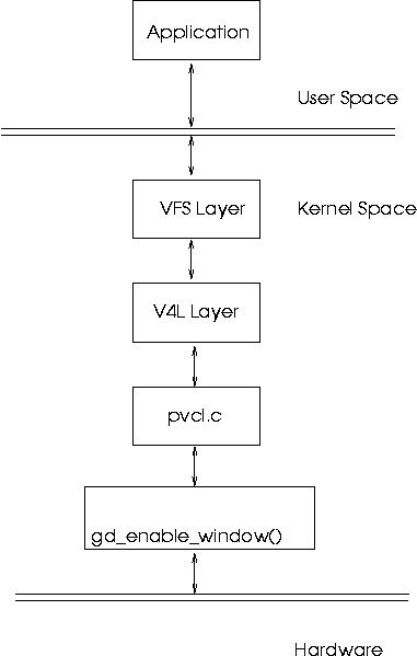
Its time now for a guided tour of an IOCTL call. Consider that instant of time at which a video4linux application, such as xawtv (see: http://bytesex.org), calls ioctl() to switch on the TV window.
The application queries the device driver for available chroma keys, and selects one. It then proceeds to fill in the background of the video window with that single colour. Overlaps are then allowed to be painted over the application window, and the video capture is then turned on. Naturally, only the non overlapping regions, ( which are filled with the chroma key background ), are filled in with video data.
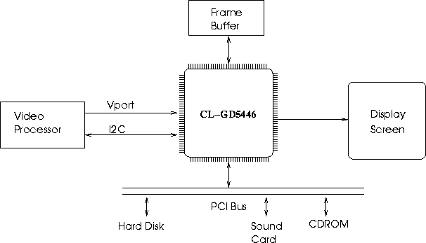
The GD-5446 has two interesting features, as far as tuner capture
is concerned. It has an I2C bus interface via two pins, and a Video
Port interface via 16 pins. The video port interface follows the ITU-656
standard for exchange of video data. Don't get scared here: Remember
that pixels can be made up of more than one byte ? eg: 16 bpp equals
two bytes. Well, somebody needed to tell chip manufacturers that in
the case of multiple bytes per pixel, transmissions between chips
needed to be done in a certain order. Take the case of YUV. Y stands
for brightness, U and V stand for the two colour components of a pixel.
Let each component occupy 1 byte (this is not true in real life YUV
4:2:2 format, but what the heck, let's illustrate to taste.). One
pixel therefore requires 3 bytes, ie; 24 bits. Here's the deal: If
you're a chip manufacturer, and you want to boast of an extra incomprehensible
line in your features list (to grab the attention of potential customers,
of course), consider the ITU-656 seal. But be-warned - once you're
sealed, the spirit of the beast is upon your chip. Video gets transmitted
only in a particular order: U-Y-V. And here's the good news: The VPX
3225D is part of the brotherhood! Ah, so now it all falls in place.
The VGA controller and the Video Processor have a clandestine path
of communication, via something called the VPort. And here's further
good news: the VPX 3225D has an I2C bus as well! Surprise Surprise
!
Ahem, alright, lets sober down a bit and figure out what this means:
Quiz time again:
Identify the master chip on the I2C bus of our Pixelview tuner card.
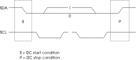
Let's take a look at SDA and SCL, the two I2C pins:
The SDA pin is the data pin. The SCL pin is the clock pin. The SDA pin may be driven either by the master or the slave, depending on the direction of data transfer. The SCL pin is driven exclusively by the master.
As Linux device driver writers, we're quite lucky. Most of the low level, pin level details are handled for us by the kernel. What we need to do is to plug in certain helper routines into the kernel. These helper routines allow the kernel to talk to the I2C bus on our tuner card. Helper routines are like sports car drivers on a cross country rally. Not only do Rally drivers know how to drive really well, they also know their cars in and out - whether its time to change the oil, or whether that front right shock absorber is leaking fluid, or when the clutch plate is close to tatters - little things like that; if there is a problem, the driver knows about it in a jiffy. The navigator, on the other hand knows the terrain, and the race route like the back of his hand. So seconds before the next hairpin curve, he shouts "one hard left coming up!", and the driver shifts down a gear, caresses the brake pedal, does a double twist on the steering wheel - and that's one less hair pin to take. Similarly, the kernel here knows the I2C protocol, and knows when the SDA and SCL pins need to be wiggled. The kernel barks orders to the helper functions, who do the actual wiggling. In order for the kernel to talk to helper functions, they need to be registered with the kernel. The kernel provides a registration function for this: i2c_bit_add_bus(). We pass it a structure defined so in linux/i2c-algo-bit.h :
void (*setsda) (void *data, int state);
void (*setscl) (void *data, int state);
int (*getsda) (void *data);
int (*getscl) (void *data);
/* local settings */
int udelay;
int mdelay;
int timeout;
struct i2c_algo_bit_data gd_bus;
gd_bus.setsda = gd54xx_setsda;
gd_bus.setscl = gd54xx_setscl;
gd_bus.getsda = gd54xx_getsda;
gd_bus.getscl = gd54xx_getscl;
udelay = 16;
mdelay = 10;
timeout = 200;
i2c_bus_add(&gd_bus);
Let me refer you to documents in the ('Documentation/i2c/') subdirectory for comprehensive details on the I2C implementation within the kernel. In particular, ('Documentation/i2c/writing-clients') is a very nicely written intro on writing I2C drivers.
Answer to quiz:
The GD-5446.
The kernel implements access to a few I2C master chips as well as a direct interface to the SDA and SCL pins. This interface is called the bit bang interface. In the case of the Pixelview Combo TV plus tuner card, we have direct access to the SDA and SCL pins of the I2C bus via SR8 of the GD-5446 VGA controller. SR8 is accessible via hardware ports 0x3c4 and 0x3c5. I've done these accesses using the gd_read_sr() and gd_write_sr() routines. Refer to (pvcl.c). Here's a description of the I2C control register, SR 8, of the GD5446:
| I/O Port Address: | 3C5h |
| Index: | 08h |
| Bit | Description |
|---|---|
| 7 | I2C SDA Readback |
| 6 | I2C Configuration |
| 5 | Reserved |
| 4 | Reserved |
| 3 | Reserved |
| 2 | I2C SCL Readback |
| 1 | I2C Data (SDA) Out |
| 0 | I2C Clock (SCL) Out |
Whenever one of the I2C bits within SR8 register is wiggled, it is reflected on the I2C bus and all slaves see the change. For example, if bit 1 of SR8 is set to 0, the GD-5446 pulls the SDA line low. If bit 0 of SR8 is set to 1, the GD-5446 pulls up the SCL line. Time to look at set_sda() and get_sda(). As usual, these two are from pvcl.c, and are stripped down for readability.
void gd54xx_setsda (int state)
{
set_bit(6, &i2c_state);
/* Set/Clear bit */
state ? set_bit(1, &i2c_state) : clear_bit(1, &i2c_state);
gd_write_sr(, i2c_state, 0x8);
What basically happens here is that gd54xx_setsda (1) pulls the SDA line high, while gd54xx_setsda (0), pulls it low.
set_scl() works similarly, except that the SCL pin is affected.
Getting the current status of the SDA pin works by reading the corresponding status bit from SR8. In this case, it is bit 7. If the SDA pin is high, bit 7 will be equal to 1. If it is low, bit 7 will be 0. This can be read into a variable, as shown below:
int gd54xx_getsda (i2c_state)
{
The first, is the concept of an adapter.
linux/i2c.h says: " i2c_adapter is the structure used to identify a physical i2c bus along with the access algorithms necessary to access it."In our case, the GD-5446 I2C bus along with the bit-bang access algorithm, make up the adapter.
Next comes the algorithm:
Here's what (linux/i2c.h) has to say about access algorithms:
"(an access algorithm) ... is the interface to a class of hardware solutions which can be addressed using the same bus algorithms - i.e. bit-banging or the PCF8584 to name two of the most common."The gd54xx_setsda(), gd54xx_getsda(), gd54xx_setscl() and gd54xx_getscl() functions, are helper functions for the bit-bang access algorithm. Consequently, they would not have existed if the GD-5446 I2C bus used some other mechanism, such as a PCF 8584 I2C interface.
The third concept we have to deal with is that of an I2C client.
Once again (linux/i2c.h) is the authoritative reference:
"(A client) ... identifies a single device (i.e. chip) that is connected to an i2c bus."In our case, we have just two clients: the VPX-3225D and the Phillips FM1216ME MK3 tuner module. The I2C protocol makes sure that only one chip is accessed at a time, by assigning certain addresses to certain chips. Therefore, every client has an address number associated with it. The VPX-3225D only responds to addresses 0x86 and 0x87 or, addresses 0x8e and 0x8f, depending on how the chip is configured. The tuner module responds to address 0xc6.
Every I2C transaction is prefixed by a target address. This must be done by the master. Only addressed slaves, may thus respond to queries from the bus master. This may also be used as a method to probe the I2C bus to see if it can detect any chips. The Linux kernel supports this kind of probing.
do:
"A driver is capable of handling one or more physical devices present on I2C adapters. This information is used to inform the driver of adapter events."At first it may seem funny that we're talking about another device driver within a device driver! But you notice that there may be more than one chip on a given adapter, and each chip needs to be programmed separately. Any piece of code, which understands the working of a piece of hardware, and programs it accordingly, may be called a driver. In this case, the driver may be just a couple of routines within a module, and there may be more than one driver, in that sense, within a kernel module.
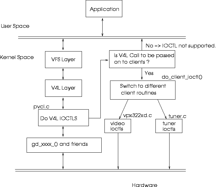
It might be instructive to note that I've implemented the I2C driver for the VPX-3225D within another file called vpx322xd.c This separates the code between the main v4l driver, and the vpx part neatly. The two drivers would talk to each other via an internal arrangement similar to that of the IOCTL call in user space. Interestingly, the driver for the Phillips FM1216ME MK3 tuner module, is already available with the 2.4 kernel, and may be compiled as a separate module. This is an example of how open source works so well. I provide the adapter and windowing functions, somebody else provides the tuner driver to work over my adapter, I have a video processor module to add to that, and yet someone else, has written the video4linux user space client, which understands the V4L API. Cool, eh ?
To understand how to code the I2C driver for the video processor (the VPX-3225D, in this case), we need to know two things - the context in which our code runs, and the environment within which it runs.
When all is said and done, the purpose of the VPX-3225D driver, is to implement instructions passed down from the application. A generic I2C driver registers something called a ``command'' function, when it registers itself with the Linux I2C core. Once registered, this command function may be called by tracing it through a list of available I2C adapters. The linked list goes this way: adapter-> clients[n]-> driver-> command , where n is the nth client on an adapter. Therefore, adapter-> clients[n]-> driver-> command() would translate to ``call the command function associated with the driver for client ``n'' which resides on adapter''. The adapter structure is of course, accessible from the main V4L driver, pvcl.c, which registered that adapter in the first place. Therefore, all clients on that adapter, and hence, all client drivers and their callback ``command'' routines are accessible from pvcl.c by simply traversing through the adapter structure.
Let's trace through an ioctl() call for switching on capture.
Thus ends the section.
The PCI bus, is the most common bus used in today's computers. (For really innocent novices: A bus, is any piece of wire or set of wires, on which more than one peripheral is connected to at the same time, and therefore has be treated as a shared resource.) Apart from speed (33MHz up-wards), the PCI bus is a plug and play bus. This has nothing to do with the wires, of course. The wires on a PCI bus are as brain dead, as the wires in my table lamp. The difference is that any device connected to the PCI bus, must behave in accordance to a set of rules called the PCI specification. Among other things, PCI devices, ie; devices which are connected to the PCI bus, need to give information to the Bus Master about the Name, Type and number of functional Chips, their preferred IRQ lines, DMA capability etc. This helps the bus master share the resources of the bus effectively. The bus master in this case, would be a proxy of the system processor, usually a ``steering device'' or a ``bridge device''. We won't go into the details here. What interests us as tuner card device driver writers are three things:
Device Identification, DMA, IRQ line allocation.
Linux provides a set of functions for accessing information about PCI devices. These functions talk with the PCI hardware, and have already obtained details about all cards which are connected. What concerns us is identifying the Chip on board. pci_find_device() fills in a structure, with the name of the card, the Vendor ID of the card, and the Chip ID of the chip on board. These IDs are available in linux/pci_ids.h. They are available there, because each of the chip manufacturers has registered their devices in a central, public database beforehand.
In the case of the Pixelview card, the task of identifying the GD-5446 is very simple. Look for the PCI_VENDOR_ID_CIRRUS and PCI_DEVICE_ID_CIRRUS_5446. If both fields are available in the card database, then the card is indeed controlled by the CL-GD5446. Look for the probing function in i2c_clgd54xx_find_card() in pvcl.c, for info about how this is done.
Like any other bus, the PCI system allows transfer of data only between one master, and one slave. The master initiates the conversation, and the slave responds with data, or requests. On the PCI bus, the master, is usually a proxy of the system processor. This chip, behaves like the system processor itself, bossing all other chips into submission. Effectively, system devices see the processor in the proxy, and obey its instructions. But the processor is a very busy chip, and cannot devote itself to transferring data between PCI chips without giving up on performance. So the bus is designed to occasionally allow other slave chips to become masters, under the delegation of the system processor. In such cases, the new master of the bus has control over the PCI bus, and can initiate any type of transfer it likes. Of course, this mastership is on a lease of time, and the moment the processor desires so, the upstart has its rights revoked and is put in its place, and the processor takes over.
Let's take the case of a tuner card, which desires to transfer data to the VGA card. The tuner card chip, indicates its desire to do so, by raising a DMA request, on a special line called DREQ, on the PCI bus. The PCI controller chip, in consultation with the processor (via other lines external to the PCI bus), grants or revokes the request. Once the request is granted, the tuner card can address the VGA chip, just like the processor would, and it could initiate a transfer of data over the PCI bus, with the system processor happily going about other jobs. If ever the processor needed to access the VGA chip as well, it would only need to revoke the tuner card's bus rights, and write to the VGA chip, as usual.
In older buses like the ISA bus, a dedicated chip called the DMA controller was used for delegated bus mastering. It was the responsibility of the system kernel to allocate resources on the DMA controller itself, and thus the advantages of DMA were limited to a small number of devices, on such busses. In the case of PCI, any chip may become bus master, and the DMA controller would be placed on the individual card itself. This would make contention of the request line, DREQ, the only bottleneck. To alleviate the problem, multiple DREQ lines are available on the PCI bus, with the PCI bus controller arbitrating between simultaneous DREQs on multiple lines.
Devices need to indicate to the processor, events which are not predictable beforehand. Such events are called asynchronous events. Examples of Asynchronous events are: The arrival of a packet of data on a network card, the opening of the CD-ROM tray, the completion of filling a frame of video data by a video processor, etc.
Asynchronous events, are indicated by devices by using a line on the PCI bus called the Interrupt Request Queue (IRQ) line. IRQ lines, are scarce resources on a bus, and the PCI bus is no exception. However, IRQ lines may be shared between devices, if there were some means to discern between multiple parties sharing the same line. The code responsible for handling IRQ requests is called the Interrupt Service Routine (ISR). If an IRQ is indicated by some chip, the processor immediately switches to the ISR. The ISR then reads registers on each suspect device, until it finds which device on the shared line was the culprit for raising the IRQ, and does whatever needs to be done in servicing that request. Servicing might include tasks like saving the newly arrived packet, flushing system buffers, or resetting the pointers within a video processor. Each of these tasks is device specific, and hence, the device driver must contain the ISR, which is registered with the system kernel, so that it may be called at Interrupt time.
Nobody writes code from scratch. The very few who do, have very specific reasons for doing so, and even then, they rely on code templates, or ideas borrowed from their own or others' code. So if you are a budding device driver writer, the best way to start would be to read through device driver code which is already available in the Linux kernel. Don't worry, nobody will accuse you of plagiarism - the Gnu Public License (GPL) under which the Linux kernel is released, actually encourages code re-use. As long as you don't make verbatim copies of somebody else's code and change the authors' name to your own, you're free to use the kernel code. Any new part of existing code, may be claimed by you. Of course, remember that any GPL code which is altered, although the changes may be copy righted to you, may only be released again, under the terms of the GPL.
Click on the following links to see the source code.
An unofficial patch of the author's Linux Driver for the Pixelview Combo TV plus TV tuner card, is available for download at http://cherry.freeshell.org/downloads/
This document was generated using the LaTeX2HTML translator Version 2K.1beta (1.48)
Copyright © 1993, 1994, 1995, 1996,
Nikos Drakos,
Computer Based Learning Unit, University of Leeds.
Copyright © 1997, 1998, 1999,
Ross Moore,
Mathematics Department, Macquarie University, Sydney.
The command line arguments were:
latex2html -no_subdir -split 0 -show_section_numbers /tmp/lyx_tmpdir12763rVg3I/lyx_tmpbuf1276gZAXat/article.tuner.tex
The translation was initiated by Cherry George Mathew on 2003-05-20
![[BIO]](../gx/2002/note.png) Cherry is a graduate in Electronics Engineering, who
lives in the Indian City of Bangalore. His favourite hobbies are
Reading novels, playing the Guitar, and Hacking Code.
Cherry is a graduate in Electronics Engineering, who
lives in the Indian City of Bangalore. His favourite hobbies are
Reading novels, playing the Guitar, and Hacking Code.